
|
News Detail
Antegrade nailing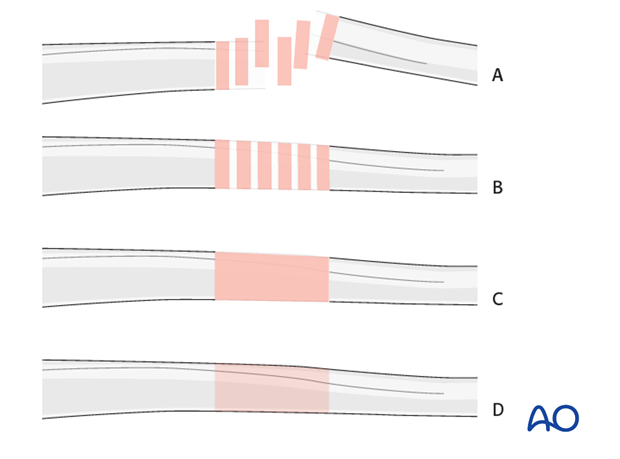 1. General considerations Reamed versus unreamed nailing In general, reamed nailing allows the use of larger diameter implants and may therefore provide greater initial stability. Some studies show a tendency towards less malunion and nonunion when reaming is performed. On the other hand, fat embolization is a concern and with the solid unreamed nails, the forces required to achieve nail torsion are higher. Most centers prefer reamed nailing as the standard procedure. For bone graft while reaming, see Note on illustrations Throughout this treatment option illustrations of generic fracture patterns are shown, as four different types: A) Unreduced fracture
2. Choice of implant and approach General consideration To gain purchase in the short proximal fragment, a dedicated cephalomedullary device is often preferred.
Alternatively, the standard femoral nail with a proximal femoral screw may be used. Insertion of a second locking screw underneath the proximal femoral screw can be considered, depending on the location of the fracture.
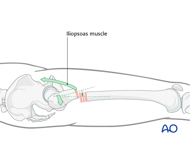
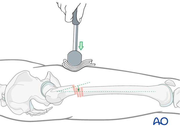
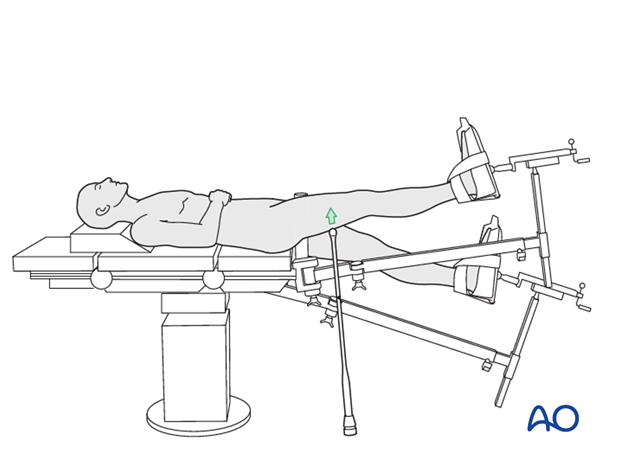
Proximal locking options The choice of the implant and the fracture configuration determines the potential proximal locking options to be considered. Choice of entry point The choice of entry point is crucial for the correct insertion of the implant and to avoid varus deformity. A The Teaching videos AO teaching video: Femur - Shaft fractures - Intramedullary Nailing with the Antegrade Femoral Nail (AFN) AO teaching video: Femur—Shaft fracture 32-B2 Intramedullary nailing with the Expert Lateral Femoral Nail (LFN) 3. Patient preparation The patient may be placed in one of the following positions: Supine position with manual traction 4. Reduction General considerations Subtrochanteric fractures represent a particular problem in terms of fracture reduction and alignment. Due to the strong forces exerted by the iliopsoas muscle, the proximal fragment is flexed and externally rotated, and can be extremely difficult to control. This may even require open reduction maneuvers to ensure correct alignment. If an anatomic reduction is not achieved, the nail will maintain the malalignment and most likely a malunion, nonunion, or implant failure will result. Therefore, the first steps of the operation are crucial to the final outcome. The reduction maneuvers in general are similar to midshaft fractures. Several options for fracture reduction are available: Depressing the proximal fragment by use of external pressure from a mallet Use of a crutch beneath the distal fragment A Schanz screw inserted into one of the fragments Use of a bone hook Use of reduction forceps (closed or open procedure) (Poller screws – blocking screws) Cerclage wire Co-linear clamp
Depression of the proximal fragment by use of external pressure from a mallet The use of a mallet can be attempted but will often fail because of the shortness of the proximal fragment and is difficult to maintain during subsequent stages of the procedure.
Elevation of the distal fragment by use of a crutch This option may only be used if the patient is on traction. A crutch is slid beneath the distal main fragment to elevate it to the level of the proximal fragment.
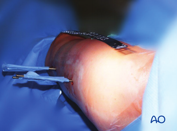
A Schanz screw inserted into one of the fragments A monocortical Schanz screw (preferably 5 mm) can be helpful for providing direct access to the displaced fragments. It is superior to reduction maneuvers through the skin.
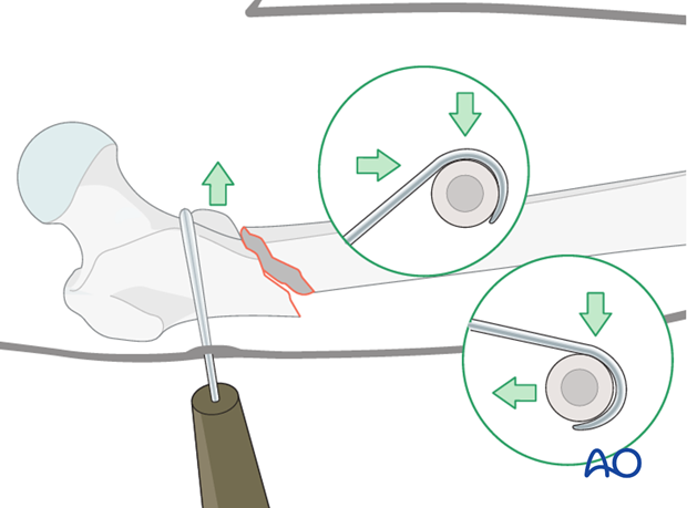
Use of a bone hook Direct reduction via a bone hook may be helpful for providing anatomic alignment. Careful insertion and manipulation must be performed to minimize soft-tissue trauma and to prevent injury to the femoral artery.
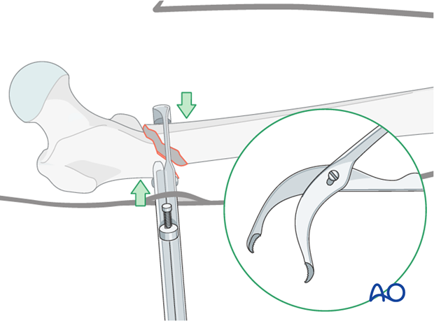
Use of pointed reduction forceps These are often required to achieve proper alignment. A pointed reduction forceps may easily be inserted but may not provide enough force. Therefore, a stronger clamp applied directly to the fracture, via a more extensive approach, is recommended.
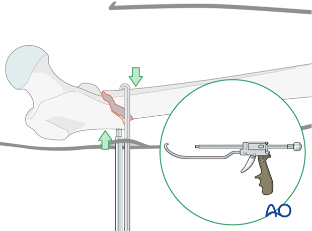
Use of colinear clamp A colinear clamp has also proven to be helpful in such cases.
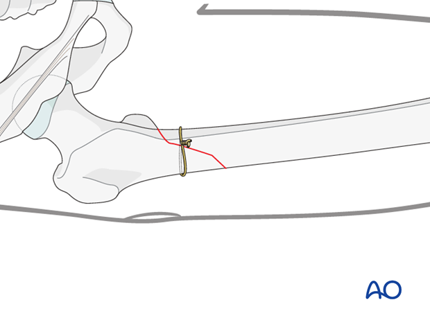
Cerclage wire A cerclage wire is also useful in simple spiral and simple oblique fractures.
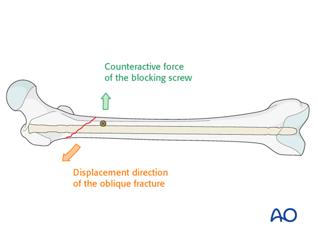
Poller screws (blocking screws) In subtrochanteric fractures the occasional use of a medial poller (blocking) screw is attempted by very experienced surgeons. It carries the danger of blow-out fracture of the proximal fragment. See also:
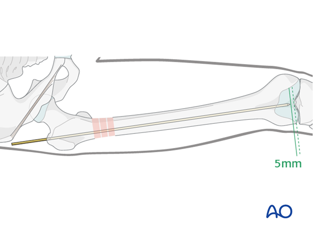
Insert guide wire A guide wire is advanced into the distal main fragment until it is about 5 mm proximal to the intercondylar notch. It is important that the guide wire be centered to prevent eccentric reaming and subsequent malposition of the nail, which can result in varus/valgus/antecurvatum/retrocurvatum malalignment. Unreamed nailing does not require a guide wire. When unreamed nailing is performed, the nail is used as a reduction tool.
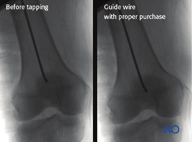
To ensure maintenance of alignment of the K-wire throughout the reaming process, it may be gently tapped to provide purchase in the cancellous subchondral bone. If this is not achieved, the guide wire may displace on removal and exchange of the reamers.
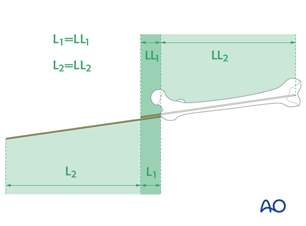
5. Determine nail length and diameter Determine nail length via guide wire (only with reamed nailing) The correct length of the nail is determined by comparing a second guide wire to the one that has been inserted. The correct placement of the guide wire in the distal canal should be assessed via image intensifier. Additionally, the second guide wire must be positioned in contact with the greater trochanter. This must be verified by image intensifier as well.
Radiographic ruler Alternatively, a radiographic ruler may be used. The tip of the ruler should be positioned in the center of the distal end of the femur. Nail length is determined by the position of piriformis fossa, not by the tip of the greater trochanter.
It is important to visualize the fracture zone by image intensifier to ensure that adequate restoration of femoral length has been achieved.
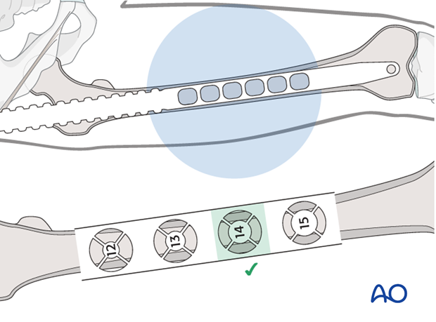
Nail diameter It is important to measure the medullary diameter at the mid portion of the femur, which represents the narrowest segment of the medullary canal. The inner cortical edge should touch with the inner numbered disk of the ruler aperture. In the illustration an inner cortical diameter of 14 mm is shown.
Consideration for special situations In multifragmentary fractures, or in open fractures with bone loss, it is safer to perform preoperative planning on the uninjured leg. In bilateral femoral fractures, the less comminuted side should be used to determine the length and diameter of the nail. 6. Reaming Insertion of reaming rod After the tissue protector has been introduced, the reaming shaft, fitted with the first reamer head, is inserted over the guide wire. Usually reaming begins with a 9 mm medullary reamer.
Sequential reamer size increase Reaming is performed in sequential steps by increments of 0.5 mm each. As soon as chatter from cancellous bone can be felt and heard, the inner cortex has been reached. This may not be the case in segmental fractures or when severe comminution is present. Adequate reaming must be performed to allow for smooth nail insertion. For example, for a nail width of 10 mm, drill bits of up to 10.5 or 11 mm diameter are used. If a very tight fit of the reamer can be detected before the desired reaming size is reached, one should consider using a smaller nail than previously planned.
Pitfall 1: Eccentric reaming Eccentric reaming can cause weakening of the adjacent cortex which may interfere with healing or even cause a fatigue fracture. Pitfall 2: Trapping of reamer by slow spinning Pitfall 3: Heat necrosis by overaggressive reaming Pitfall 4: Rapid thrusting/systemic fat embolization
This may cause pulmonary embolization of medullary fat, which in turn may lead to pulmonary dysfunction (lower image in the enlarged view shows an example of fat embolization through the right atrium).
Special situation: conversion from an external fixator to an intramedullary nail Because the external fixator is still in place, the Schanz screws must be partially withdrawn to allow the guide wire, the reamers, and later the nail, to pass through. The external fixator is held in place by monocortical purchase to assure that the fracture remains stable. The external fixator also acts as a joystick for the reduction.
7. Nail insertion Connecting handle to nail The insertion handle is connected to the nail by the corresponding connecting screw. It is attached using the hexagonal screwdriver through the hole in the insertion handle. It is recommended that the nail be inserted manually and rotated about 90 degrees from its point of entry to its final orientation.
Introduction of nail Under control with the image intensifier, the nail is pushed down as far as the fracture zone. After the driving cap has been fixed to the insertion handle, the nail is further advanced into the medullary cavity by gentle hammer blows, whilst verifying the position of the tip of the nail under the image intensifier.
Passing the fracture zone It is important that the tip of the nail does not become trapped in the distal main fragment because blow out fractures can occur. Each gentle hammer blow should advance the nail. Do not force the nail through a tight canal – if necessary, re-ream to another 0.5 mm diameter.
Assessing proper nail insertion The nail is then completely inserted. This is assessed by using an additional K-wire that marks the upper end of the nail.
Assessing proper nail insertion for very proximal fractures (cephalomedullary nails) The position of the cephalomedullary screws should be centered in the middle portion of the femoral neck, or slightly below. An axial view must be taken to ensure proper centering of the implant in the femoral head and neck.
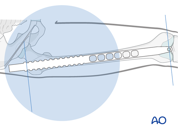
8. Nail locking - general considerations Special situations: 130° antegrade locking When a dedicated cephalomedullary device is not available and the fracture configuration permits, a 130° antegrade locking option can be considered.
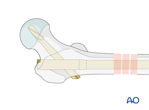
Special situation: associated femoral neck fracture The system used for the ipsilateral femoral neck and shaft fracture must have the ability to biomechanically solve the midshaft femoral and femoral neck dilemma. This means that the nail must have at least two possibilities for screws into the femoral neck. Another option would be as shown in the diagram.
Dynamic or static locking Simple transverse non-comminuted fractures are stable and fracture healing may be enhanced by dynamic locking. Comminuted fractures require a length stable construct so stable locking is mandatory. Slotted locking holes can be used for dynamic locking while small circular holes are used for static locking.
Use all locking options If a standard nail is inserted, it is wise to use multiple proximal locking options.
Pearl: secure screw by use of a suture If the contact between the screw driver and the locking screw is lost, the screw may move within the soft tissue and become extremely difficult to capture. To prevent this time-consuming complication, the locking screw should be lassoed with a strong absorbable suture.
9. Distal locking Verification of nail position Before locking, the correct position of the nail and the rotation of the femur must be verified. If no traction table is used (ie, using the freehand technique) the cable method may be used. In this approach, a line is drawn from the iliac spine across the patella to the cleft between the first and second toes. If rotation is correct, this line will pass over the mid line of the patella. The radiological landmarks of the center of the femoral head, the center of the knee and the center of the ankle joint should all be in line if the mechanical axis of the femur is correct. Another method of assessing rotational reduction is to compare the cortical thickness above and below the fracture. If a shaft fracture is multifragmentary, the image intensifier cannot be used to assess the analogue cortical diameter on both sides of the fracture.
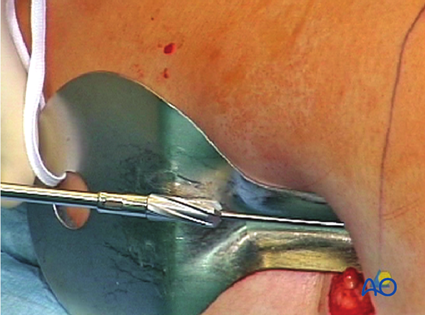
Distal aiming For distal locking, the image intensifier is brought into a strict lateral position. The distal hole must be seen as a perfect circle and the tip of a scalpel is projected into the center of the hole.
This guides the stab incision down to the femoral cortex.
Screw insertion technique The radiolucent drive helps to position the drill bit so that the locking screw can be properly inserted. While the locking hole is drilled, the assisting surgeon must prevent the lower extremity from moving in order not to miss the target hole. The length of the locking screw is determined, using the appropriate depth gauge. Then the locking screw is inserted.
If a radiolucent drive is not available, the projection of the tip of the drill bit should be placed as centrally as possible (see image). Start drilling but assess the position of the tip of the drill bit repeatedly, with the drill temporarily uncoupled.
Pearl: If the contact between the screw driver and the locking screw is lost, the screw may move within the soft tissue and become extremely hard to capture. To prevent this time-consuming complication, the locking screw should be lassoed with a strong absorbable suture. Pitfall: If the screw holes are not perpendicular to the nail, the locking screw may become trapped and may not be advanced properly.
Second locking screw The second locking screw is inserted into the distal locking hole. After distal locking, an axial blow to the knee region may be used to reduce any fracture distraction. Alternatively, when distal locking is completed prior to proximal locking, a slotted hammer can be used to pull back the locked nail and the distal fragment.
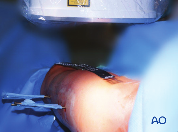
Completed distal locking The image shows the distal locking completed.
Pitfall: screw loosening Care should be taken to capture the far cortex to prevent toggling when the patient is mobilized. This would lead to early loosening of the locking screw. In the image shown, the proximal locking screw is of correct length, but the distal one is marginally too short.
10. Intraoperative radiological assessment Assessment of rotation The profile of the lesser trochanter on the intensifier image is compared with that of the contralateral leg (lesser trochanter shape sign). Before positioning the patient, the profile of the lesser trochanter of the intact opposite side (patella facing anterior) is stored in the image intensifier. The illustration shows the lesser trochanter of the intact opposite side.
Malrotation In cases of malrotation, the lesser trochanter is of different profile when compared to that of the contralateral leg. Care should be taken to assess rotation with the patella facing directly forwards.
Matching of the lesser trochanter shape After distal locking, the correction is achieved by using the handle of the nail insertion device. Thereby the distal main fragment can be rotated in relation to the proximal main fragment.
11. Proximal locking Proximal aiming device If proximal locking is performed before distal locking, it is important to verify the correct position of the distal end of the nail under the image intensifier before the proximal aiming device is attached to the insertion handle.
Preparation for screw insertion The sites of the skin and fascial incisions for the drill bit and locking screws may be determined after the drill sleeve assembly has been in the holes of the aiming device. The length of the locking screws is read from the calibrated drill bit. The correct length is confirmed antero-posteriorly using the image intensifier. The insertion handle should not be removed until the correct placement of all the locking screws has been verified.
Drill sleeve to bone contact The drill sleeve must be in close contact with the bone at all times since it is important for the measurement of the locking screws. Close contact is maintained by pressing down on the sleeve with the contralateral thumb.
Verification of locking screw placement A final x-ray in two planes should be obtained in all cases to verify the exact locking screw placement.
Insertion of end cap An end cap might be inserted depending on the choice of implant. 12. Wound closure and assessment of alignment Wound closure The procedure ends with the closure of the fascia and the skin as separate layers.
Assessment of alignment Before the patient is moved from the fracture table, rotation of the leg is observed clinically and compared to the contralateral leg. With the femur now stable, it is possible to perform a thorough examination of the knee joint to rule out additional ligamentous injuries. 13. Aftercare Compartment syndrome and nerve injury Close monitoring of the femoral muscle compartments should be carried out especially during the first 48 hours, in order to rule out compartment syndrome. Postoperative assessment In all cases in which radiological control has not been used during the procedure, a check x-ray to determine the correct placement of the implant and fracture reduction should be taken within 24 hours. Functional treatment Unless there are other injuries or complications, mobilization may be started on postoperative day 1. Static quadriceps exercises with passive range of motion of the knee should be encouraged. If a continuous passive motion device is used, this must be discontinued at regular intervals for the essential static muscle exercises. Afterwards special emphasis should be placed on active knee and hip movement. Weight bearing Full weight bearing may be performed with crutches or a walker. Follow-up Wound healing should be assessed regularly within the first two weeks. Subsequently a 6 and 12 week clinical and radiological follow-up is usually made. A longer period may be required if the fracture healing is delayed. Implant removal Implant removal is not mandatory and should be discussed with the patient, if there are implant-related symptoms after consolidated fracture healing. 14. Case Preoperative images with ipsilateral femoral neck, femoral shaft, and distal femur condylar fracture in a 20-year-old patient. This fracture combination can be extremely difficult to treat, and carries a high risk of delayed healing and late complications. Intraoperative view of patient on fracture table. Intraoperative fluoroscopic view of femoral neck fracture with a small amount of traction applied. Midshaft fracture in femur, in traction but not reduced. Insertion of initial T-handle reamer for nail placement. Ball-tip guide wire at fracture site before fracture reduction. It was not possible to achieve closed reduction of the shaft fracture. A small incision was used to access the midshaft fracture. Small Hohmann’s retractors were inserted to expose the fracture. The incision was enlarged to allow a bone clamp to be placed on each of the main fragments. This allowed the fracture to be reduced so that it was possible to pass a ball tipped guide wire across the fracture site. Reaming was performed over the guide wire. A femoral nail with proximal cephalomedullary locking options is inserted. Once the nail is inserted to appropriate length, the femoral neck fracture must be reduced and held with guide wires. This image shows the first guide wire being inserted through the lateral cortex. Lateral image showing guide wire with fractured femoral neck. Slight distraction of the femoral neck can still be seen. A second guide wire is inserted; note that the femoral neck fracture is still distracted. Intraoperative image showing the first screw inserted into the femoral head. Clinical intraoperative image showing proximal screw insertion into the femoral head using a jig. Intraoperative image showing final screw placement. Lateral intraoperative image of final reduction showing slight malreduction of the femoral neck, but now with minimal distraction. Postoperative AP pelvis image. Postoperative images showing complete fixation of the ipsilateral femoral neck, femoral shaft, and distal femur condylar fracture. 4 weeks postoperative X-ray showing good fracture alignment, but no callus. 17 weeks postoperative images showing initial femoral neck healing without displacement, but still minimal callus at the midshaft fracture. 39 weeks postoperative images show the femur completely healed. 1.5 years postoperative images show that both the femoral neck and shaft fractures are solidly united.
|


Shanghai Carefix Medical Instrument Co., Ltd.China
滬ICP備16042301號(hào)-1 (滬)-非經(jīng)營性-2016-0122 滬食藥監(jiān)械生產(chǎn)許20101725號(hào)