療器械有限公司")
|
News Detail
Pitfalls and limits of locking plates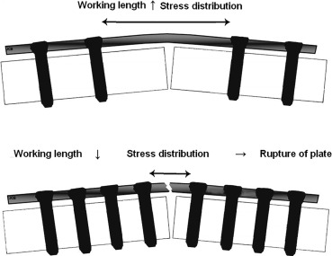 Abstract The use of locking plates relies on novel mechanical and biological concepts: the bone healing is endochondral because of the elasticity of the constructs. Preoperative planning is required to determine the Keywords Locking plate Locking screw Fracture Biomechanics Complications 1. The introduction of locking plates has expanded the scope of This lecture will address the following questions about locking plates based on our team's experience and the recent literature: ? what principles guide their use? ? what particular features and difficulties must we be aware of? ? what are the challenges surrounding removal? ? what are their limits? 2. It is essential that surgeons have a good understanding of the biomechanics of the resulting constructs, as they can be completely different than those of conventional plates. The surgical technique is still evolving since these are fairly new implants. The learning curve is very long for these implants and numerous failures have occurred 2.1. A new biomechanical paradigm appeared with locking plates. They follow the principles of external fixators. The stable interface between locking screws (LS) and locking plates (LP) means they do not need to make direct contact with the bone. Their subcutaneous position means they also behave like internal fixators 2.2. Bone healing with LP differs depending on which part of the bone is fractured. In the epiphyseal area, anatomical reduction of the intra-articular fragments is needed with the best possible contact between fragments. Absolute stability, which occurs with the LP acting as a neutralization plate, allows bone healing. In the diaphyseal area, alignment (coronal, sagittal and rotational) and bone length are restored without the intermediate fragments being exposed or directly reduced. Relative stability is obtained with LP that is sufficient to allow 2.3. There are four principles of use Compression of diaphyseal fractures: first, one end of the plate is secured with a LS, then the other end with a conventional screw placed off-center in a dynamic compression hole, which results in compression of the fracture site. This principle is similar to Neutralization of diaphyseal fractures: after the interfragment screws are in place, the LP is positioned. This increases the interfragment stability and maintains compression at the same level. Bridging of comminuted diaphyseal or extra-articular metaphyseal fractures: the part of the plate directly over the fracture site has no screws, which allows the plate to absorb loads by bending. The construct is elastic. Combination: placing conventional screws in standard holes results in compression of intra-articular fracture lines. The anatomically reduced fragments are then secured to the plate with LS. Next the epiphyseal block is secured to the The application of these principles can differ depending on the brand of plate 2.4. Two criteria are used when selecting the length of LPs: working length and total length. These determine the construct's elasticity, which can lead to atrophic non-union if overly stiff and hypertrophic nonunion if overly flexible The working length is the distance between the first two LS located on either side of the fracture site. This is the area to which stresses are applied. It determines the construct's stiffness The construct must be stiff and also elastic to allow the micromotion needed for healing. For a metaphyseal or diaphyseal fracture, leaving three or four empty holes over the fracture site will produce the desired construct elasticity (Fig. 1). For
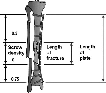
Download :?Download high-res image (180KB) Download :?Download full-size image Fig. 1. The total length of the LP also impacts the construct's stiffness. It must be 2–3x longer than the length of the fracture site for comminuted fractures and 8–10x longer for simple fractures. Five holes are needed on either side of the fracture site
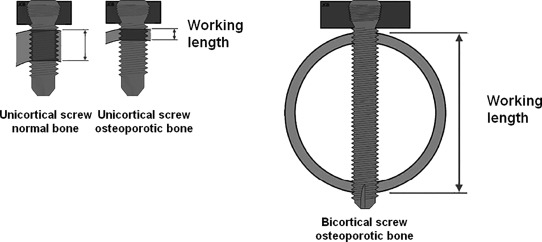
Download :?Download high-res image (191KB) Download :?Download full-size image Fig. 2. 2.5. The position of LPs relative to the bone cortex determines the strength of the construct. While LPs act as internal fixators and preserve the 2.6. The number of LS should be minimized (alternating between screws and empty holes) because of the risk of concentrating loads where the screws are concentrated and of It is recommended to use 3 LS by diaphyseal bone segment in the lower limb, which is loaded in compression, and 4 LS per diaphyseal bone segment in the upper limb, particularly in the The LS density (number of screws divided by number of holes in the plate) must be less than 0.5 in diaphyseal and metaphyseal zones to ensure the construct is not too stiff The LS are positioned near a complex fracture to increase its rigidity and further away from simple fractures to ensure the construct is elastic enough to stimulate osteogenesis In osteoporotic bone, LS have much better purchase in bone than do standard screws 2.7. In a hybrid construct, LS and standard screws alternate in the plate. This provides better torsional and bending resistance than a construct with LS only. Conversely, a construct with LS only has more axial stiffness 2.8. When selecting the LS length, their strength is based on the working length, which itself is determined by the thickness of the bone cortices. Bone anchoring, compression and torsional resistance, and breaking load are better with bicortial than unicortical LS. Unicortical LS should not be used for fixation in the diaphyseal zone. In osteoporotic bone, it becomes more important to use biocortical LS as the cortex gets thinner
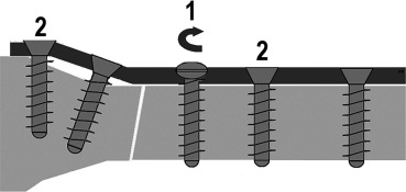
Download :?Download high-res image (197KB) Download :?Download full-size image Fig. 3. 2.9. Plates for polyaxial LS allow the screws to be inserted freely with the trade-off being lower strength. Polyaxial LS with freely chosen alignment help to get around anatomical or implant-related obstacles. They also make it easier to secure epiphyseal fragments. They are useful during the fixation of From a biomechanical point of view, polyaxial LS have the same strength as monoaxial LS when they are aligned perpendicular to the plate, but quickly lose strength when they are not. With a 10° angle, the hold of a LS is reduced by 50%. However, if this applies to a single screw, the overall stability of the construct is not really compromised For monoaxial LS, not aligning the screw's axis in the threads of the LP has negative consequences on its strength, thus it is essential to use alignment and screwing instrumentation In summary Select LP that are long enough to have several open holes over the fracture site to ensure the construct's elasticity. Fix every diaphyseal fragment with 3 bicortical LS distributed along the entire plate's length, leaving at least one empty hole between each LS. Locking head screws do not allow compression. Polyaxial LS are strongest when they are aligned perpendicular to the LP. It is critical to use all the provided instrumentation during implantation. 3. 3.1. The steps for reducing a fracture are standardized. A fracture cannot be reduced on a LP. Once a LS has been placed in the bone segment, adding more screws will not move it. If using LP that only accept LS, this means the plate should only be locked once the fracture has been reduced. Since LP allow It has also been shown that poor reduction due to a mechanically insufficient construct results in poor healing with the plate breaking due to delayed union or non-union Reduction without using the plate is especially difficult when performing Conversely, when using LP that also have holes for standard screws, one standard traction screw can be placed in a standard hole for the initial reduction on the plate. The bone fragment is placed against the plate. If the plate is anatomical, it can then be used as a reduction guide. The construct's stability is ensured by the LS without altering the initial reduction. This insertion sequence–standard screws then locking screws–is critical (Fig. 4).
Download :?Download high-res image (159KB) Download :?Download full-size image Fig. 4. 3.2. There is no haptic feedback when tightening locking head screws. In fact, tightening of the LS occurs simultaneously in cortical or 3.3. Use of self-tapping locking screws means that there is no haptic feedback during drilling or screwing since they occur simultaneously. During unicortical application, their mechanical properties are like those of unicortical locking screws. If they are too long, they will touch the non-drilled second cortex, leading to incorrect positioning of the LS in the LP. During bicortical application, they can be too short, making them mechanically equivalent to unicortical LS. If they are too long, they will overshoot the cortex and can damage critical structures on the other side of the plate. Correct LS length can only be achieved by measuring the required length after drilling or by verifying it on fluoroscopy 3.4. The primary drawback of monoaxial LS is that their direction is predetermined. There may be another implant or prosthetic stem in their path, making insertion impossible or limiting them to unicortical hold. For anatomical LP used in the extremities with monoaxial LS with fixed direction optimized for anatomical and biomechanical reasons, there is a danger of intra-articular LS placement. The classic example is 3.5. The minimally invasive percutaneous osteosynthesis (MIPO) technique consists of subcutaneous and/or submuscular and extraperiosteal implantation of a bone plate after having slid the plate against the bone through a small opening, without exposing the fracture site. This results in smaller It can be done with LP with specially designed instrumentation that allows the plate to be manipulated and to easily locate the LS holes in the plate through the skin. Fluoroscopy images must be taken at every step to verify the progress
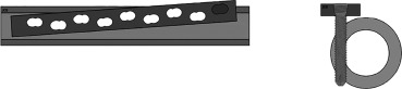
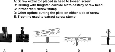
Download :?Download high-res image (66KB) Download :?Download full-size image Fig. 5. 3.6. Use of LP for fixation of 3.7. In osteoporotic bone, LS help to reduce the risk of the screws pulling out or backing out. The construct is less stiff because the bone cortices are thinner, and the bone trabecular density is reduced. In this case, In summary Locking head screws do not allow The fracture must be reduced before locking heads screws are added. LP instrumentation is required for percutaneous fixation of a reduced fracture. The MIPO technique is very demanding. 4. Removing LP once the fracture has healed is challenging and unpredictable, but the situation can be resolved. The biggest challenge is loosening the locking head screws In some cases, the pattern on the head of the LS was destroyed when it was inserted (screw tightened and loosened multiple times, screwdriver pattern damaged and not perfectly hex-shaped, screw insertion finished with motorized drill), which means it cannot be unscrewed. Thus it is a good habit to immediately change any screw in which the head pattern is damaged during implantation, to use an intact screwdriver and to tighten screws fully by hand (not a motorized drill) to prevent this complication. Using more robust Stardrive? profile screws can help to reduce this problem. Most often there is mechanical locking or jamming (not cold welding) between the LS thread and the threaded hole on the LP. This most often occurs with 3.5-mm diameter titanium hex pattern monoaxial locking head screws. The jamming mechanism is not univocal. Often the screw was over-tightened initially because the torque wrench provided in the instrumentation set was not used, which can alter the threads on the LS and LP. In other cases, the screw alignment was incorrect during tightening because the drill guide was not used or was used incorrectly, which leads to the screw jamming. To reduce the risk of jamming as much as possible during the initial fixation, it is essential to use all the available instrumentation: drill guides and sleeves, torque wrench fully intact pattern when tightening LS. The MIPO technique has a higher risk of incorrect alignment guide placement because the LP is not seen directly. The drill guide will not be aligned correctly, which means that the holes drilled for the LS and the insertion of the LS will also be incorrect. There is also a risk of damaging the head pattern of LS when the screwdriver does not engage properly with the screw For these reasons, before removing a LP, the surgeon must be aware that it could be impossible to loosen the LS, thus have a high-quality hex screwdriver and additional instrumentation available When a LS cannot be loosened, or the head pattern is damaged, the first step is to place a screw extractor (a tapered screwdriver with a reversed thread) into the screw head; this may be sufficient to loosen the screw. Another option is to cut the LP on either side of the LS and to use it as a screwdriver to loosen the entire construct. If the screw still cannot be loosened, the LP can be released by destroying the head of the LS by drilling it with a tungsten carbide bit or by cutting the plate around the LS. Afterwards, the stump of the LS can be removed using vise-grips. If it still cannot be loosened (because it is integrated into bone or it does not stick out enough), it can be extracted with a trephine (Fig. 6).
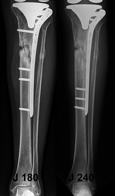
Download :?Download high-res image (151KB) Download :?Download full-size image Fig. 6. These problems all extend the surgery time, can cause attrition of the soft tissues due to the released metal debris and have a risk of infection. Use of trephines increase the risk of a perioperative fracture. In summary Challenges with removing LS mainly occur with 3.5-mm titanium locking head screws with hex pattern. The best way to avoid this problem is to use all of the provided instrumentation when inserting the screws. These difficulties can be resolved by using appropriate instruments. 5. 5.1. The risk of the LP breaking below a screw hole or at the screw/plate junction can be reduced by making sure the construct is not too stiff due to inadequate LP working length or excessive number of LS (Fig. 7).
Download :?Download high-res image (379KB) Download :?Download full-size image Fig. 7. The diagnosis of nonunion is often confirmed by the plate breaking. The late rupture of the LP or LS is timely as it allows the micromotion leading to bone union For simple fractures requiring compression, which depends on the type of fracture, not the bone involved, a stiff construct in which the two fragments do not make contact leads to nonunion and fatigue failure of the plate One variation is the simultaneous rupture of the LS below their junction with the plate, also due to an overly stiff construct. It results in “en bloc” pull-out of one end of the plate, without healing being achieved
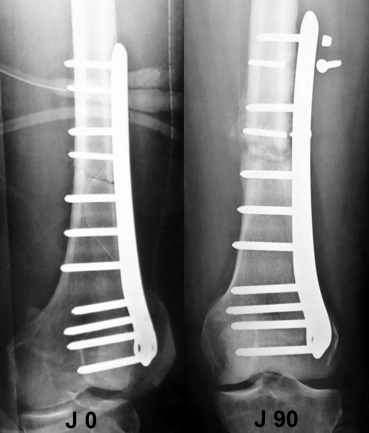
Download :?Download high-res image (281KB) Download :?Download full-size image Fig. 8. Thus fixation of intracapsular 5.2. The periosteal callus may be asymmetric, especially in fractures of the distal third of the femur, which is clearly less developed on the side of the LP. The micromotion due to elasticity, which allows even development of the fracture callus, only occurs on the side opposite the LP/LS construct. To control this risk, the working length of the LP should be increased, or more elastic titanium plates Conversely, an overly flexible construct will result in hypertrophic nonunion 5.3. The risk of plastic deformation in the middle of the plate can be reduced by placing it as close as possible to the cortex. When there is more than 5 5.4. The risk of late fracture of the 5.5. Certain situations increase the risk of LP mechanical failure: ? fixation of ? fixation of epiphyseal fractures is difficult because they are often unstable, especially since the fracture site cannot be compressed by the LS and the bone is osteoporotic; ? intra-articular fractures with metaphyseal comminution and comminuted extra-articular fractures are unstable (e.g. ? epiphyseal fractures with medial comminution tend to displace into varus (e.g. Thus using only a LP on the lateral side for fixation of bicondylar tibial plateau fractures must be considered depending on the type. For 5.6. These so-called “biological” failures are related to the histological features of the fractured bone and not the implant characteristics. There is also mechanical weakness of the bone relative to the implant. The modes of biological failure of LP are screw pull-out and cut-out or impaction of the LS. These risks are greater when the bone is osteoporotic, which means that early rehabilitation must be performed carefully along with return to weight bearing before bone healing is achieved. 5.6.1. Screw pull-out corresponds to “en bloc” and simultaneous pull-out of the LS from the bone at one or both ends of the plate. In some cases, the LS pull out with a piece of bone around them. In the epiphyseal area, a one-piece LP construct usually provides sufficient stabilization thanks to divergent or convergent LS anchoring, with the three-dimensional constructs increasing the resistance to screw pull-out from In the diaphyseal area, convergent and divergent LS and constructs with longer LP have better pull-out strength These 5.6.2. Cut-out or impaction of the LS with intra-articular penetration can occur in the cancellous epiphyseal area. These displacements are those of the epiphyseal fragment of low quality bone that move around fixed LS. This leads to loss of reduction of the epiphyseal fracture. In the best-case scenario, the epiphyseal LS impact and penetrate into the cancellous bone. In the worst-case scenario, the epiphyseal LS exit the epiphysis and become intra-articular. These two complications most often occur with proximal humerus and These fixation failures are due to insufficient bone quality and large initial displacement of the fracture fragments before their reduction, even though the constructs are mechanically sound 5.7. Rehabilitation and immediate weight bearing is only allowed after perfect fixation is achieved and validated on postoperative x-rays. Biomechanical studies show that in normal bone, weight bearing can be allowed without risk if the gap between fragments is less than 1 When the construct is mechanically sound, LP and fixed-angle LS allow early resumption of weight bearing as the loads are transmitted directly to the LP by the LS, with no risk of fixation failure at the LP/LS junction However, LP and variable-angle LS do not allow early weight bearing, in principle For MIPO, early weight bearing is possible for extra-articular, simple and/or simple 6. Biomechanical studies have evaluated various types of constructs and their mechanical properties. The literature has helped to validate the theoretical hopes associated with this type of fixation. However, the recent literature has also highlighted the technical difficulties and failures associated with locking plates. The main reasons for failure are insufficient planning of the surgical technique, which is very demanding, particularly when The fracture must be reduced first without locking the screws in the plate because indirect reduction on the plate by a locking screw is impossible. The constructs must be the correct length and strength which means the surgeon must be familiar with the principles and rules guiding use of these plates. Thus the construct must be elastic with a limited number of regularly spaced locking screws that alternate with empty holes. Even though locking plates have better theoretical primary stability, the construct's hold is limited by the fracture's complexity, the quality of the reduction and the bone's biological quality. If the construct is mechanically Funding source None. Disclosure of interest The authors declare that they have no competing interest. References
|

Shanghai Carefix Medical Instrument Co., Ltd.China
滬ICP備16042301號(hào)-1 (滬)-非經(jīng)營(yíng)性-2016-0122 滬食藥監(jiān)械生產(chǎn)許20101725號(hào)

%22 \t %22https://www.sciencedirect.com/science/article/pii/_blank)
%22 \t %22https://www.sciencedirect.com/science/article/pii/_blank)
%22 \t %22https://www.sciencedirect.com/science/article/pii/_blank)
%22 \t %22https://www.sciencedirect.com/science/article/pii/_blank)
%22 \t %22https://www.sciencedirect.com/science/article/pii/_blank)
%22 \t %22https://www.sciencedirect.com/science/article/pii/_blank)
%22 \t %22https://www.sciencedirect.com/science/article/pii/_blank)
%22 \t %22https://www.sciencedirect.com/science/article/pii/_blank)